Engineering Aero and Industrial Gas Turbine Technologies

Zafer

Experienced member
Messages
4,470
Reactions
6 7,143
Nation of residence
Turkey
Nation of origin
Turkey
EDIT: Moved to strategic technologies section.

Mod edit: Reply in reference to https://defencehub.live/threads/engineering-stuff.1343/page-3#post-37175

Seems like it is only the torque tube that they are introducing to adjust the pitch angle of the power turbine blades is the innovation this time instead of a purely mechanical actuator. This will increase the VTOL performance quite a bit and perhaps will make going for it worthwhile.
 
Last edited by a moderator:

Nilgiri

Experienced member
Moderator
Aviation Specialist
Messages
9,315
Reactions
96 18,896
Nation of residence
Canada
Nation of origin
India
Seems like it is only the torque tube that they are introducing to adjust the pitch angle of the power turbine blades is the innovation this time instead of a purely mechanical actuator.

Yah the larger concept is well known for quite some time...especially in cold section where its very fundamental to do (Variable inlet guide vanes etc)....given low --> hi basic pressure flow and thus large surge issues if you dont have variable restrictor available as the compressor section got bigger with time.

Hot section equivalent of that (VATN) presents lot more challenges especially in aviation jet engine given temperature, creep and sealing issues when you introduce conventional actuators etc...and then have to consider the weight increase too. The surge consideration is not a factor given Hi --> Low flow....so this lessens the driver for it compared to compressor. But it is ongoing RnD area like everything else, it has seen lot more application in commercial gas turbine given weight consideration is not so great for those.

I have patent papers from GE sitting on desk somewhere from the 60s...and actually every decade since...because they have the scale on ground to implement this technology before computing era.

What is unique to this new recent development is they are going to the actual stator and rotor of rotating turbine itself...extending the concept well past guide vanes (for raw flow introduction parametric design/modelling).

The SMA alloy is basically going to act like a heat-driven cam for it:


I have been following this development for a cpl years or so, the key recent breakthroughs relate to the CFD verification process from what I can understand....given its rotating section modelling (complex, novel) compared to inlet/guide vane modelling (easier and established).

SMA alloy also will be big breakthrough in coming years for such things as VAFN where you can adaptively control/cam the fan exit nozzle area...and this means you can make the bypass ratio larger than we have now for each core.


This will increase the VTOL performance quite a bit and perhaps will make going for it worthwhile.

Indeed, given the performance envelope range that VTOL uniquely needs. This will be something of interest for you to follow given your project you are working on.

I am unsure of your knowledge in the area currently but if you (or anyone else here) want to gain a more complete working knowledge of gas turbines and jet engines in more practical sense (past any textbook etc), this channel really is the best to do it...the guy has dedicated so much time to it and has done a phenomenal job:


I would also be happy to answer any questions and queries to best of my ability (with time available etc) in this thread regarding the subject matter.
 

Zafer

Experienced member
Messages
4,470
Reactions
6 7,143
Nation of residence
Turkey
Nation of origin
Turkey
Yah the larger concept is well known for quite some time...especially in cold section where its very fundamental to do (Variable inlet guide vanes etc)....given low --> hi basic pressure flow and thus large surge issues if you dont have variable restrictor available as the compressor section got bigger with time.

Hot section equivalent of that (VATN) presents lot more challenges especially in aviation jet engine given temperature, creep and sealing issues when you introduce conventional actuators etc...and then have to consider the weight increase too. The surge consideration is not a factor given Hi --> Low flow....so this lessens the driver for it compared to compressor. But it is ongoing RnD area like everything else, it has seen lot more application in commercial gas turbine given weight consideration is not so great for those.

I have patent papers from GE sitting on desk somewhere from the 60s...and actually every decade since...because they have the scale on ground to implement this technology before computing era.

What is unique to this new recent development is they are going to the actual stator and rotor of rotating turbine itself...extending the concept well past guide vanes (for raw flow introduction parametric design/modelling).

The SMA alloy is basically going to act like a heat-driven cam for it:


I have been following this development for a cpl years or so, the key recent breakthroughs relate to the CFD verification process from what I can understand....given its rotating section modelling (complex, novel) compared to inlet/guide vane modelling (easier and established).

SMA alloy also will be big breakthrough in coming years for such things as VAFN where you can adaptively control/cam the fan exit nozzle area...and this means you can make the bypass ratio larger than we have now for each core.


Indeed, given the performance envelope range that VTOL uniquely needs. This will be something of interest for you to follow given your project you are working on.

I am unsure of your knowledge in the area currently but if you (or anyone else here) want to gain a more complete working knowledge of gas turbines and jet engines in more practical sense (past any textbook etc), this channel really is the best to do it...the guy has dedicated so much time to it and has done a phenomenal job:


I would also be happy to answer any questions and queries to best of my ability (with time available etc) in this thread regarding the subject matter.
Thanks a lot for the detailed response. Things get interesting as such tech becomes closer to reality.
 

Saithan

Experienced member
Denmark Correspondent
Messages
8,144
Reactions
21 18,734
Nation of residence
Denmark
Nation of origin
Turkey
This may sound like a stupid question, but surely the angle of the blades are locked in place and aren't meant to be rotated to on and off.

e.g. a jets or helicopters system will adjust the blades according to weather condition to attain maximum efficiency before take off.
 

Nilgiri

Experienced member
Moderator
Aviation Specialist
Messages
9,315
Reactions
96 18,896
Nation of residence
Canada
Nation of origin
India
This may sound like a stupid question, but surely the angle of the blades are locked in place and aren't meant to be rotated to on and off.

e.g. a jets or helicopters system will adjust the blades according to weather condition to attain maximum efficiency before take off.

No (many parts inside are indeed adjustable/variable during operation), let me tell you why, hopefully without confusing.

I might as well input the time now to save time later (as I figure lot of people in this forum are interested in this subject and can have a future reference to use).

First a basic overall illustration of the system to make reference easy:

jet engine.gif


Some more terminology for the innards:

Guide/Vane: Louvres/blades that control/regulate introduction of fluid (do not rotate) at each major "handoff" (intake to compression, compression to combustion, combustion to extraction, extraction to exhaust), plays no direct part in compression or extraction

Stator: Blades that are fixed (do not rotate), they are joined to the casing, sometimes vane and stator are used interchangeably since they are fairly similar in most respects being non-rotatable... (bad/lazy/non-precise habit/convention but it is what it is)

Rotor: Blades that rotate, they are joined to the spool/shaft that transmits torque

You find all 3 of these in both cold and hot section.

Rotors and stators in cold section work to compress the working fluid (air)

Rotors and stators in hot section extract energy from the working fluid (combusted air) to provide work/torque to cold section by way of a spool/shaft

Example (wiki) animation of rotors (moving) and stators (stationary) in the cold section:

Axial_compressor.gif


Basic way this is done (I am skipping lot of details just to give overall idea):

Compressor basic process (Input Energy ---> Compress air):

A) Take torque given by turbine through spool and transmit to its rotors.

B) Rotor ---> stator (impart rotation to flow and then squish it against stator) and then repeat to get more compression (i.e more rotor and stator sequencing)


Combustor basic process:

(my current main work area for last few years)

A) Mix fuel with this compressed air

B) Make it go boom (create extremely angry energetic air)


Turbine basic process (Air expanding ---> Extract energy):

(essentially reverse of compressor)

A) Stator ---> rotor (direct the angry energetic air to do work on a rotor)..and repeat to get more extraction (i.e more stator and rotor sequencing)

B) Provide torque to spool (Connect to step A of compressor)


Certain thermodynamic limits + materials limit extent all of this in today's jet engines:

Thermodynamic efficiency about 50% - 60% currently (chemical bond energy --> mechanical energy)
Propulsive efficiency about 70%+ (mechanical energy --->propulsive energy)

Total combined efficiency at about 40%+ (i.e chemical bond energy of fuel+oxygen converted to useful work i.e thrust)

Industrial Gas turbines can achieve much more than 40% (i.e 60% or higher) given propulsive energy efficiency not a factor (mechanical energy output is just used as is).

=======================================

Now why and where do we make certain bits of the vanes, stators and rotors, be able to change their angle during operation?

Simply put, its because the operating conditions are not uniform during a typical session (similar reason you need gear/transmission for internal combustion engine).

It is most heavily and directly noticeable at and in the cold section/compressor.

There is a wide variety of operating conditions: inlet fluid pressure, inlet fluid speed, rpm, power/torque applied from turbine etc..

Consider the wide range of conditions the compressor sees regarding different input velocity (given the aircraft moves appreciably from rest) and different input pressures (as aircraft changes altitude) relative to those found within its operation (fluids geeks call it a control volume).

Consider the cruise thrust of engine is often just 20 - 30% of take off thrust. Most aircraft spend most time at cruise obviously, but you still need that 80% or so extra thrust for take-off and other operating realm...this gives huge torque range a compressor sees.

Consider the compressor is doing something quite unnatural in forcing fluid to move from low pressure to high pressure (by doing considerable work on it).

All these and still further considerations (which I wont go into for now) have to be taken into account simultaneously.

The unnatural direction of flow (and its different/unnatural end conditions w.r.t intake and compressor) mean if you achieve "too much compression" relative to what the ambient condition can handle and/or calls for....means you can get compressor stall (parts of compressor stop compressing as the work they do is insufficient to overcome the back pressure being generated) and even compressor surge (where the sudden drop in work from compressor means the torque from turbine dissipates by way of more rpm) and the flow basically reverses and you have very serious bad condition.

These all dictate what's known as the "surge line", a basic operating realm (w.r.t things like inlet relative velocity, pressure, torque etc) that the compressor must stay within.

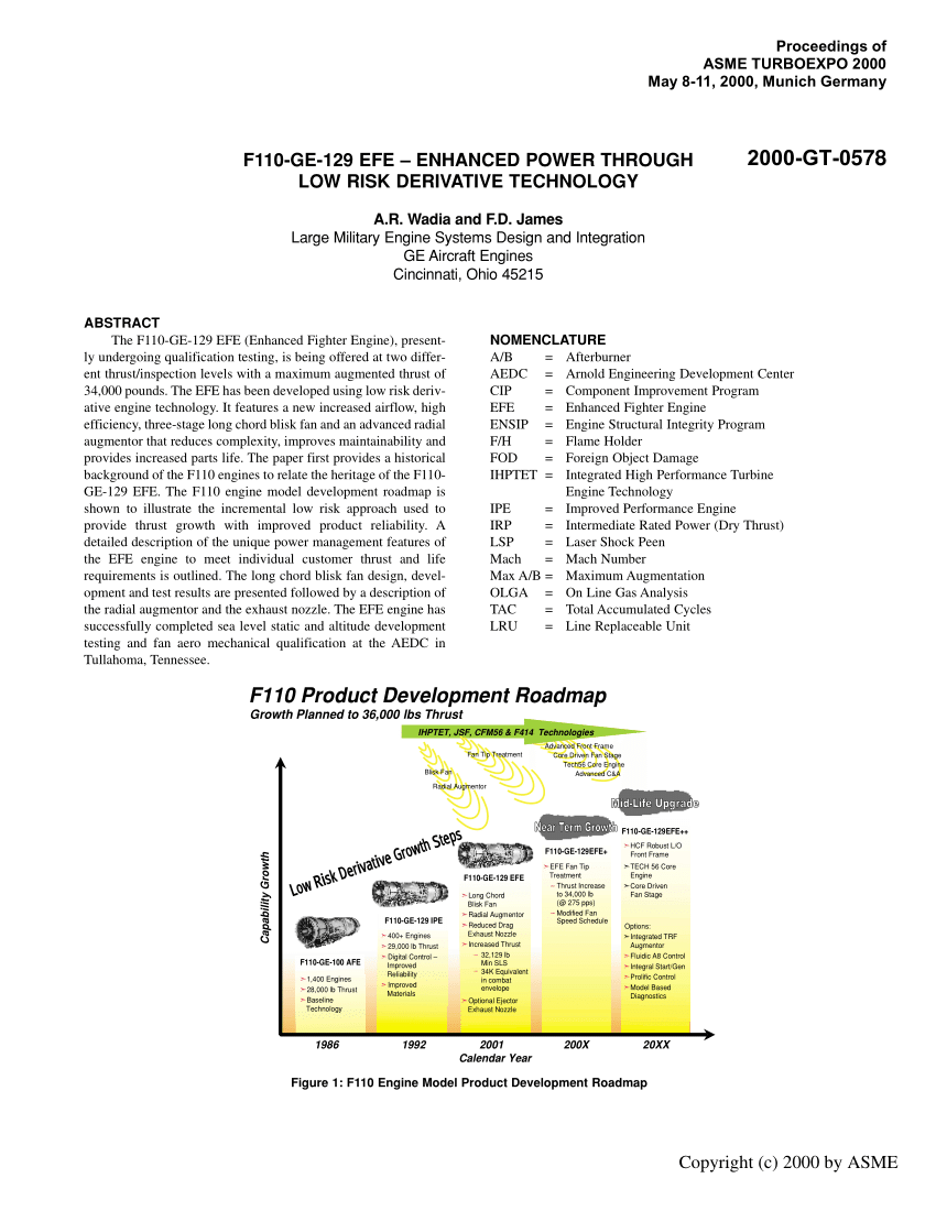
You can certainly take the fact that an aircraft in typical flight spends most time at certain numbers regarding these (at cruise)...say you have typical 80% cruise time in a 100% start to end of the engine) and design fixed geometry in everything. This is exactly what the earliest jet engines did.

But to do that comes with severe losses and operating realm restriction (the earliest developers found that out quite quickly and even concurrently during research).

Thats why the first compressors used (with fixed geometry only) could only be big enough to achieve 5:1 compression ratio, go past that and you reach surge line = BAD!

Those early systems first work around was to actually bleed off air in compressor stage to prevent over-compression (and surge line approach)....but there is only so much you can do this before you hit brick wall and it gets very inefficient and even impossible....especially given the big efficiency + performance + economic driver is to get higher and higher compression ratio.

This is why the RnD quite early (in the 50s itself and arguably even before that) shifted to finding ways to actuate parts of the compressor section to make them variable (and more optimal) during operation...given the wide extent of the operation regime crucial parameters.

These include things like Variable Inlet Guide Vane (VIGV) and Variable Stators as first priority to offer the best ratios (complex math and science and engineering underlies this all) of resistance, transmittance and interaction with the incoming air.

Examples of this:

(Large industrial gas turbine VIGV):

(Same gas turbine, this time assembled and both VIGV and variable stators):

(VIGV and variable stators of much smaller T58 turboshaft, variability seen around 2.40 time mark):

Now the turbine (hot section) is the compressor in reverse essentially so it doesnt have the surge consideration that drives this fundamentally like in the compressor (i.e to have variable geometry stuff inside).

That is you can say it (turbine) doesnt see quite the same diverse range of operating inputs (relative to what it does and wants to do at any given moment) that the compressor does.

The turbine is basically a caveman you can say, its fairly happy and content, its job is simple and pretty brutal...compared to more picky debonair finicky compressor with its top hat and tux.

That's why it really was not worth it so long to move variable geometry considerations to hot section (though it has always been looked at and researched) given there are severe losses and compromises with conventional actuators doing this especially.

But now with smart materials and smart electronics and smart computing, even turbine section is now up for grabs for efficiency improvement (past being fixed to being just good at "cruise" condition) using variable geometry (VATN and variable stators and even variable rotors there too) and that is what the earlier posts are about (US army research team etc.)

Essentially VTOL turbofan and rotorcraft turboshaft especially have much more diverse profile of operation (compared to just having 80% cruise profile) and thus have massive immediate design driver for turbine RnD on top of compressor "established" RnD.

=============================================================================================

I have decided to create new thread for this post and will move some of the earlier replies from the engineering thread to give it some context.

I feel over time we can develop this thread to be a good archive for Jet Engine + Gas Turbine technology, esp to try give layman approach to those interested in the subject.

It is of course a high level research area for lot of countries, and given this is international forum, maybe this archive can be referenced and promoted over time (both within forum but also externally to gain more membership/interest here etc) to get more discussion, QnA, FAQ, analysis etc as it relates to other threads in this forum. I will do best I can with time I can spare with what people may enquire/discuss in here.

@Cabatli_53 @Webslave @T-123456

@Test7 @Kartal1 @#comcom @Combat-Master @ANGMAR @Predator @Vergennes @Sinan @500

@Saiyan0321 @Joe Shearer @VCheng @anmdt @Madokafc @Indos @Gautam @Paro @UkroTurk @xenon5434 @Bogeyman @Dante80 @Milspec @Zapper et al.
 
Last edited:

VCheng

Contributor
Think Tank Analyst
Messages
488
Reactions
535
Nation of residence
United States of America
Nation of origin
Pakistan
I feel over time we can develop this thread to be a good archive for Jet Engine + Gas Turbine technology, esp to try give layman approach to those interested in the subject.

Please include the metallurgy needed, if possible.
 

Nilgiri

Experienced member
Moderator
Aviation Specialist
Messages
9,315
Reactions
96 18,896
Nation of residence
Canada
Nation of origin
India
Please include the metallurgy needed, if possible.

Yes after new years, I plan to go about it by first defining the core aka "the" gas turbine (the commonality to every variant) and making that the primary subject of study.

Then I figure I will go from start to end w.r.t the story of an air molecule for that core.

The "journey" will include not only metallurgy it sees but every kind of material used (metals, ceramics) and broader technique used to handle it....along with the processes/rationale behind them without going too science-y on it. Will have to put finger to wind few times to see what the heading is on all that with the audience interest.

Lastly explore the variants (and their real applications etc) in their respective appropriate detail as time/interest dictates here.
 

Anmdt

Experienced member
Naval Specialist
Professional
Messages
5,151
Solutions
2
Reactions
97 22,951
Nation of residence
Turkey
Nation of origin
Turkey
I will be pleased in detail when i have some time,
Great thread @Nilgiri , thanks a lot.
 

Nilgiri

Experienced member
Moderator
Aviation Specialist
Messages
9,315
Reactions
96 18,896
Nation of residence
Canada
Nation of origin
India
Last "intro" teaser of 2020.

If you want to impress someone with your knowledge and strong understanding on this first issue (jet engine innard variability) more succinctly...

Or you simply want a TL;DR version (of my earlier large post here) using something more day-to-day etc:

Take any typical modern jet engine/gas turbine today:

Bring a magic wand (or some awful more mundane equivalent like a manual override of engine control logic/system, whichever is easier to acquire)

This "wand" with a wave turns everything inside the modern jet engine to a fixed angle (say w.r.t optimal cruise condition) like it was in the good old fashioned grampa days jet engines... like @Saithan reasonably intuited... (Agent double-o four?...Yes...The name's Jumo, Junkers Jumo).

If you want low drama event: Wave the wand first, Fuel up and press the engine start....the compressor will immediately stall = you ain't going anywhere bucko

If you want high drama event: Switch the order...Fuel up + Press engine start first (get it to an idle/taxi rpm etc) and then wave the wand

...the compressor will stall (far more intensely) and likely surge too given rpm. Far more loud nasty stuff than the low drama sequence.

Pro-tip: The high drama event should ofc never be done during flight.

Both cases, you ain't going anywhere till you wave that magic wand again (hopefully reversible) and make those innards variable again.

This is a very near-equivalent of how it would go with a typical modern conventional IC-based system (say a car) on the ground with appropriate system translations:

Say the wand would do the system equivalent of "fixing" the transmission (with a wave) and make it all direct-drive (1:1 gear ratio) only (say optimal "cruise" again aka say 4th gear available only)...so you engine start + release brake etc, set to 4th gear + add throttle+rpm intensely...and see how far you get..

Only difference somewhat are that jet engines are so (compressor) sensitive + big (relative to initial starting+idling conditions), that idle rpm (no need to throttle it) is more than enough to stall it with wrong "transmission" "setting" in the innards.

More broadly speaking, the working fluid in a jet engine really is part and parcel of the purely mechanical transmission + crankshaft equivalent in an ICU in many ways...though both are heat engines.

Thus one can summarise the working fluid (air) has arguably a far broader performance scope in a jet engine w.r.t conventional IC engine.

This is specifically because of the difference between the Otto cycle (and variants) and Brayton Cycle (and variants) if you are into thermodynamics.

That is w.r.t both idealized requirements and practical application of these cycles....driven by such things as reciprocation vs constant flow (of working fluid) on the (mechanical) work vector(s)

That is larger 1st principles subject maybe left for another time to explore.

Up next (in 2021): What is the "Core"? (Hint, its basically grampa)


I wrote this all up real fast, without dbl-checking so I might edit later if I or another finds mistakes.

Reminder to (those who liked*/viewing/interested) to "watch"/reply in this thread if you would like for updates to appear in alerts (if you haven't already)...I believe the default setting on forum is if you watch or reply a thread you get alerts in your feed. This is useful for any general thread you are interested in forum more broadly.


* "Likers" that may want alert feed: @Cabatli_53 @Saithan @xenon5434 @#comcom @Combat-Master @UkroTurk @Webslave @Test7 @Kartal1 @Saiyan0321 @Madokafc @Zapper @Indos
 

Madokafc

Experienced member
Think Tank Analyst
DefenceHub Diplomat
Messages
5,903
Reactions
4 10,020
Nation of residence
Indonesia
Nation of origin
Indonesia
Last "intro" teaser of 2020.

If you want to impress someone with your knowledge and strong understanding on this first issue (jet engine innard variability) more succinctly...

Or you simply want a TL;DR version (of my earlier large post here) using something more day-to-day etc:

Take any typical modern jet engine/gas turbine today:

Bring a magic wand (or some awful more mundane equivalent like a manual override of engine control logic/system, whichever is easier to acquire)

This "wand" with a wave turns everything inside the modern jet engine to a fixed angle (say w.r.t optimal cruise condition) like it was in the good old fashioned grampa days jet engines... like @Saithan reasonably intuited... (Agent double-o four?...Yes...The name's Jumo, Junkers Jumo).

If you want low drama event: Wave the wand first, Fuel up and press the engine start....the compressor will immediately stall = you ain't going anywhere bucko

If you want high drama event: Switch the order...Fuel up + Press engine start first (get it to an idle/taxi rpm etc) and then wave the wand

...the compressor will stall (far more intensely) and likely surge too given rpm. Far more loud nasty stuff than the low drama sequence.

Pro-tip: The high drama event should ofc never be done during flight.

Both cases, you ain't going anywhere till you wave that magic wand again (hopefully reversible) and make those innards variable again.

This is a very near-equivalent of how it would go with a typical modern conventional IC-based system (say a car) on the ground with appropriate system translations:

Say the wand would do the system equivalent of "fixing" the transmission (with a wave) and make it all direct-drive (1:1 gear ratio) only (say optimal "cruise" again aka say 4th gear available only)...so you engine start + release brake etc, set to 4th gear + add throttle+rpm intensely...and see how far you get..

Only difference somewhat are that jet engines are so (compressor) sensitive + big (relative to initial starting+idling conditions), that idle rpm (no need to throttle it) is more than enough to stall it with wrong "transmission" "setting" in the innards.

More broadly speaking, the working fluid in a jet engine really is part and parcel of the purely mechanical transmission + crankshaft equivalent in an ICU in many ways...though both are heat engines.

Thus one can summarise the working fluid (air) has arguably a far broader performance scope in a jet engine w.r.t conventional IC engine.

This is specifically because of the difference between the Otto cycle (and variants) and Brayton Cycle (and variants) if you are into thermodynamics.

That is w.r.t both idealized requirements and practical application of these cycles....driven by such things as reciprocation vs constant flow (of working fluid) on the (mechanical) work vector(s)

That is larger 1st principles subject maybe left for another time to explore.

Up next (in 2021): What is the "Core"? (Hint, its basically grampa)


I wrote this all up real fast, without dbl-checking so I might edit later if I or another finds mistakes.

Reminder to (those who liked*/viewing/interested) to "watch"/reply in this thread if you would like for updates to appear in alerts (if you haven't already)...I believe the default setting on forum is if you watch or reply a thread you get alerts in your feed. This is useful for any general thread you are interested in forum more broadly.


* "Likers" that may want alert feed: @Cabatli_53 @Saithan @xenon5434 @#comcom @Combat-Master @UkroTurk @Webslave @Test7 @Kartal1 @Saiyan0321 @Madokafc @Zapper @Indos

When you got older and climbing the ladder of position in your respective jobs, the more you tend to forget technical detail of young people and the more you tend to only know how much the products and solution bring the profit.
 

Saithan

Experienced member
Denmark Correspondent
Messages
8,144
Reactions
21 18,734
Nation of residence
Denmark
Nation of origin
Turkey
A request for bettering my understanding at some point 🤗

Airflow from inlets through the core ( how it’s compressed/behaves) at different stages. Max/Min volume comparing grandpa designs vs. modern designs.

1609061807152.gif

do the first 3 fans work in unison, or separate with regard to regulating the amount of air compressed to the core part.

Thus we avoid the high drama scenarios. 🤔
 
Last edited:
A

adenl

Guest
Thought I would share this article about the enhancement of the F110-GE-129 into the F110-GE-132 engine:


Attachments

  • GT2000-578.pdf
    668.2 KB · Views: 289

Nilgiri

Experienced member
Moderator
Aviation Specialist
Messages
9,315
Reactions
96 18,896
Nation of residence
Canada
Nation of origin
India
Airflow from inlets through the core ( how it’s compressed/behaves) at different stages. Max/Min volume comparing grandpa designs vs. modern designs.

Yes let me get a few posts started and done from beginning to end (inlet to exhaust), it will probably involve something of what you are looking for...and you can call for more clarification etc as needed all along the way if something feels unclear etc.... that kind of question and answer is really best way because there are things I take for granted lot of time (in my head) that don't register much to me to explain further etc....but it may not be the case for others.

For Max/min volume I am unsure what you are talking about...are we talking about compression ratio?

Overall pressure ratio is a more correct term given this is not directly the same thing of volume ratio as what you see with a piston system like I.C car engine etc

It was at best around 5:1 for best grampa jet engines.

Around 60:1 for sonny boys today (commercial high bypass).

Around 30:1 at most if sonny boy is in airforce etc and wants to spend too long a time at high speeds (which can melt the last section of compressor from the heat generated by that....so there is need to restrict max compression given the materials we have to handle it and accept the trade-off of less efficiency etc).

You can see the basic change in performance and efficiency envelope here....we are making use of every chemical bond in the jet fuel go a lot lot further than before....as things like compression ratio and RPM are directly related to thrust and sfc (specific fuel consumption) etc.

Its all very similar to cars etc....like you technically could use a single belt drive kind of transmission like the very first grampa cars in existence had....but you get huge trade-off on performance and efficiency given whats available energy wise by the otto cycle. We moved very quickly to sonny-boy cars (even the ford model T is really an older sonny boy w.r.t this) that made of multiple gear ratios to handle different regimes of operation best....rather than constrain everything for utter 1st gen mechanical simplicity....that has long been forgotten about now even given many generations of sonny-boys are way old now heh.

do the first 3 fans work in unison, or separate with regard to regulating the amount of air compressed to the core part.

Everything in the cold section (after inlet) is designed ultimately to provide compression (except for the very last part known as the "diffuser" which is the "handoff" for the combustor coming up, but more on that later). This is true whether it be "fixed" grampa or "variable" sonny boy.

These "first 3" aren't fans...they are just bigger blades + stators (representatively given) just like what follows behind them.

The sequencing goes IGV (inlet guide vane) ---> Rotor 1, Stator 1, Rotor 2, Stator 2 etc... the number you reach at very end is the number of compression stages (each stage compresses the air by up to 1.6 times in jet engines). This sequencing is very important too as the rotor must come first before its equivalent stator for the whole thing to fundamentally work. Will be discussed in more depth later.

They first 3 are bigger, the middle ones are smaller, and the final ones are the tiniest given the pressure increasing with each stage and need to keep the flow velocity the same (given how these are related to each other w.r.t Area of flow).

It can be seen here (about 0.45 mark onwards...blades first, stators (case) next):


Thus we avoid the high drama scenarios.

Well they all work to the compression achieved at the end, its really that compression number that matters the most to a lower RPM + throttle setting. If its too high (compression relative to rpm caused by throttle input), the thing will stall and/or surge....especially given the time lag for lot of these things to respond in the low rpm environment (jet engines noticeably work far more efficiently at high rpm and high speeds, so lot of things are designed for that regime and time spent there etc...and thus you need extra care and control for lot of parameters in other regimes of operation).

Hence the need to restrict the compression (by IGV and/or stator variability) for low rpm regime of sonny-boys today given their peak (at take off, cruise etc) compression ratio (technically overall pressure ratio, but the terms are often used interchangeably) can run up to about 30:1 for military jets and 60:1 for commercial.

But grampa jets long proved that 5:1 is really the most you can have (for peak compression) if you dont have options to restrict at low rpm....i.e the low rpm reality becomes the overriding design ceiling for cruise....i.e low rpm reality was the primary consideration essentially (given simplicity of making things all fixed angle at the time)...and you got what take-off and cruise and other performances you could from it (not great basically).

Sonny boy like Icarus wanted to fly even higher and better (but hopefully not "too high" like that story and the Kansas song).

Thus we have situation today (sonny boys) where we design for take-off, cruise etc as design ceilings and make the low rpm reality be secondary by making it's compressor insides more variable/adjustable (by a control logic for it) so the engine can start up + idle + operate in those regimes etc by having compression restricted suitably.
 
Last edited:

Nilgiri

Experienced member
Moderator
Aviation Specialist
Messages
9,315
Reactions
96 18,896
Nation of residence
Canada
Nation of origin
India
Thought I would share this article about the enhancement of the F110-GE-129 into the F110-GE-132 engine:


Yes blisk technology is active RnD area. PW guys like me and GE fellas have jokes we share when we come across each other somewhere (w.r.t blisk dev, manufacturing and QC)....because there is lot of competition between us on the thresholds....and all related inertia/inheritance from decisions made by whomever was running all our teams 30 years ago (sometimes even longer ago than that)....people's names only we recognise I suppose so I won't bore folks here.

I feel we (PW) are overall ahead in blisks, we have automated a huge deal 10 years ago on specific things (with 3 - 4 specific German design teams that aided greatly on it) that are paying off now (GE went couple different routes and are now catching up)....but GE have lot of cards up their sleeve too (and beat us soundly on lot of other areas of jet engine), so lets see.

RR is more mysterious entity to me past their most noticeable achievements...they are on other side of pond with their more niche system structure and corporates and lobbies there. I have not met more than a dozen or so of their engineers, its largely too few to form impression of where they stand w.r.t us going forward. But their larger inertia faced some setbacks (at crucial time in 90s) by lack of innovation on some key things that GE and PW did, and it reflects in market share now....given by far thats driven by commercial sector key numbers in the engines.
 

Philip the Arab

Contributor
Think Tank Analyst
Messages
1,333
Reactions
4 2,222
Nation of residence
United States of America
Nation of origin
Jordan
How easy are single use turbojets(Cruise missiles, loitering UAVs) to develop and manufacture compared to those long life ones used in aircraft?
 

Nilgiri

Experienced member
Moderator
Aviation Specialist
Messages
9,315
Reactions
96 18,896
Nation of residence
Canada
Nation of origin
India
How easy are single use turbojets(Cruise missiles, loitering UAVs) to develop and manufacture compared to those long life ones used in aircraft?

Far easier. The severe design challenges (from multiple sustained heat+stress cycles leading to a major design challenge known as creep on top of regular fatigue) in the turbine are much lower since its just one time use as just one example.

Materials available to produce from expand significantly, tolerances get more lax = cheaper + easier.
 

Saithan

Experienced member
Denmark Correspondent
Messages
8,144
Reactions
21 18,734
Nation of residence
Denmark
Nation of origin
Turkey
Significant advancement by GE. This will be a real game changer. They further solidify their overall lead in the field with this.

Would it be possible to make it easier to digest :), also I'd love it if you would continue with the lessons. There is so much going on, but I trip over cool stuff as I start looking for a bit information on just BSc stuff.


Nilgiri

Experienced member
Moderator
Aviation Specialist
Messages
9,315
Reactions
96 18,896
Nation of residence
Canada
Nation of origin
India
Would it be possible to make it easier to digest :), also I'd love it if you would continue with the lessons. There is so much going on, but I trip over cool stuff as I start looking for a bit information on just BSc stuff.


Basically its a turbofan that is optimised in both regimes of operation. (supersonic and subsonic).

Remember a (traditional, non adaptive) turbofan today has its turbojet core (sets highest speed) and fan (sets highest efficiency).

You have to pick one as the primary objective for the engine, and the 2nd gets relegated as secondary one to "make do" with what is essentially fixed by the primary objective

....i.e do you want to be supersonic or do you want to be efficient.

When you pick (for commercial domain) efficiency first, it becomes the case you cannot even go supersonic (there really is no point given the fan and bypass size ratios needed for high efficiency...that make supersonic travel impossible).

In military domain though, all supersonic aircraft do have significant mission time in subsonic realm as well, so it makes sense to not be satisfied with the efficiency compromise there.

Hence an adaptive cycle wants to have a pretty different cycle available for just subsonic (rather than what is there now with how good a supersonic optimised one is "stuck" with in subsonic realm)....and makes sense to be driven from the military application side first.

Essentially it would involve a larger bypass ratio and fan, and flow regimes + innovations to shut down parts of that when you want to go supersonic and go more "core only" etc...

An extreme version of another variable cycle platform was the blackbird, which one can say did a similar thing but for the supersonic ---> high supersonic transition....in that it derived most of its (higher regime) thrust from a ramjet bypass regime around its turbojet core....by modifying the flow regime by inlet cone position and inner geometry:


Modifying flow regime like this is what would be done for adaptive cycle turbofans too....with use of inner geometry distribution and various ramps and vanes in the bypass area (that now become more viable with rise of smart materials and sensors).

============================================

I will pick up the jet engine series once I get more time (hopefully later in year)....unfortunately work (and other real life matters) has really piled on this year more than I anticipated....delaying other stuff I plan for this forum as well. But all in good time.

W.r.t jet engines (or any such combustion engine really) It is all in the end a matter of how you impart energy to a working fluid (air in this case) and the capacities + feedback effects on the materials available for this task. That will be the approach I take from beginning to end.

@VCheng @Anmdt @Test7 @T-123456 @Cabatli_53 @Yasar et al.
 

Follow us on social media

Top Bottom