
Stealth is too important of a subject to be discussed just under KAAN or any other forum. So I think it deserves it's very own section.
One of the most simplified hopefully accurate information on STEALTH, regarding RCS comparisons.
Did you guys know even the ancient stealth airplane F-117 attacked 1600 targets inside HEAVILY AD armed Saddam's Iraq without ever being close to be in danger?
Will we be in any diffierent of a situation if finally impending war breaks out because of our countless potential conflict issues with Americans?
March 31, 2017

VITA Standards Organization
Instead of laboriously converting the db values for all the different fighter jets mentioned in my previous article, there's a nifty table with most of the conversions done for us. <http://www.globalsecurity.org/military/world/stealth-aircraft-rcs.htm> Using this table will also allow me to escape the clutches of the unwritten laws of journalism too. They state that readership will decline by 50 percent for every formula in an article, and by 75 percent if you show any calculations. Many good papers and articles exist on the web that expose the intricacies of RCS if you want to dig deeper into this topic. For this article, we’ll just use the m2 values from the table and skip the joys of the math.
To read more Warfare Evolution Blogs by Ray Alderman, click here.
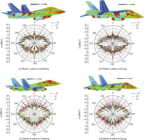
Before we get into this, other complications need to be mentioned. The RCS of an aircraft depends on its aspect, the orientation of the target to the radar source. Any aircraft will have a smaller RCS from the front, and show-up bigger from the side or the rear. Looking at the table values, their numbers seem to be based on the frontal aspect, the lowest RCS of the aircraft. Also, some fighter jets have their largest RCS from the rear, due to the exhaust nozzles. And, RCS depends on the wavelength (frequency) of the radar signal and how far away the target is. But we’ll ignore these pesky details for now. Just consider the numbers we use here as the best RCS values for each aircraft. For comparison, an average man has an RCS of about 1m2.
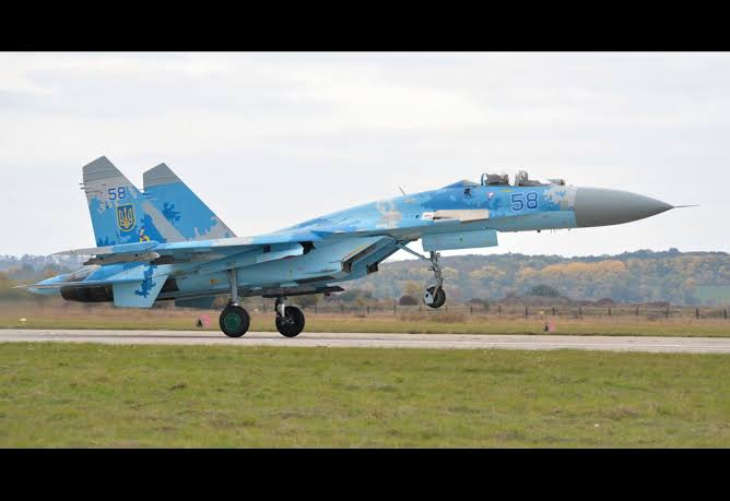
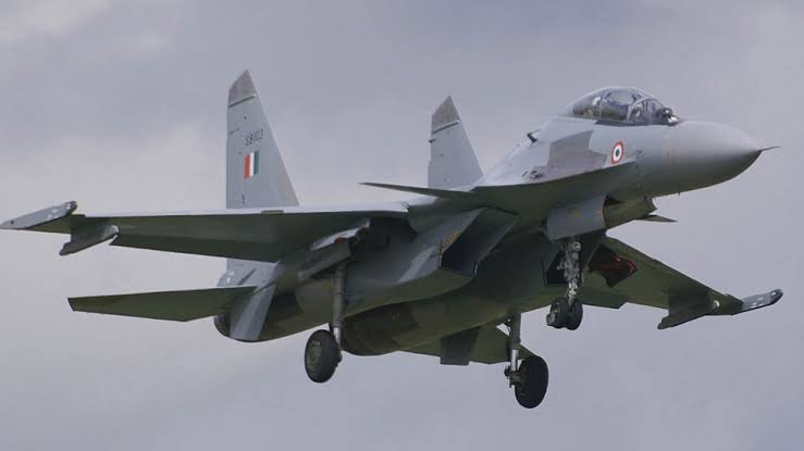
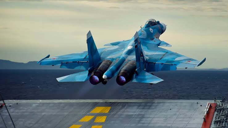
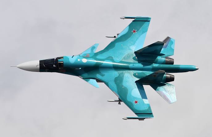
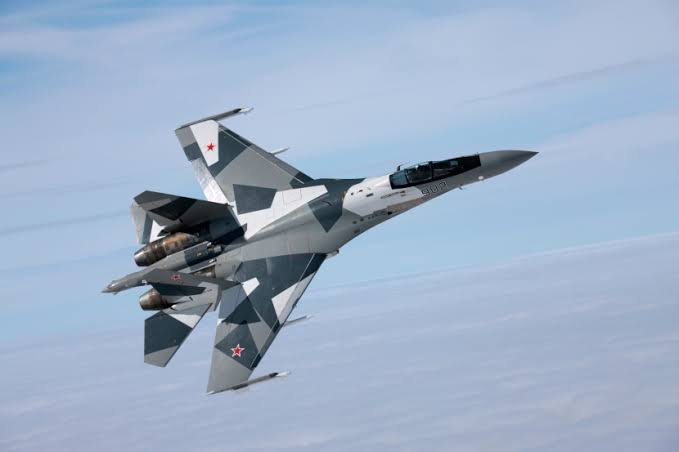
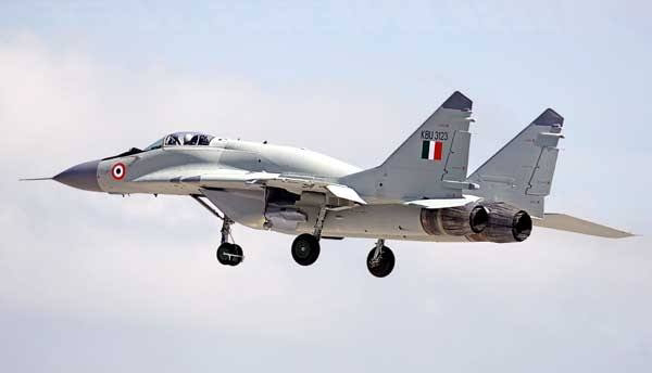
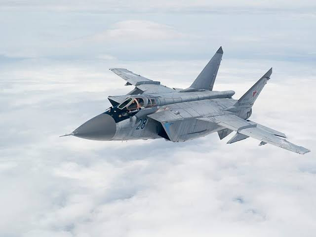
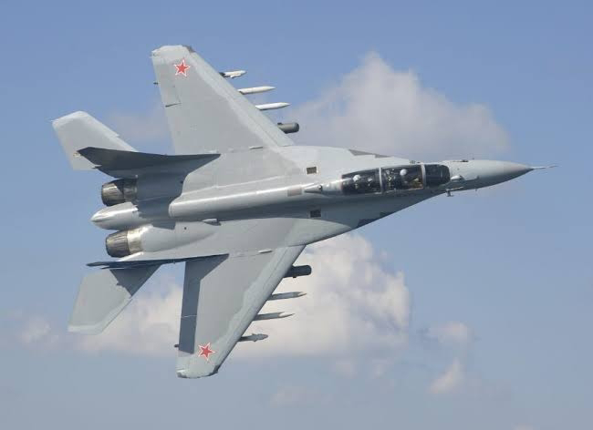
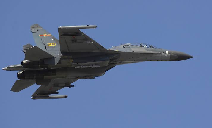
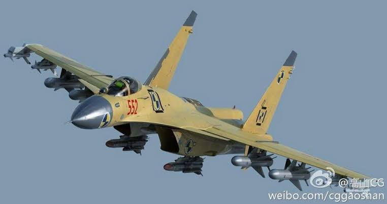
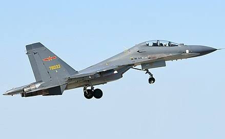
- In my last blog, we talked about Russia’s older 4G MIG-XX, 4.5G SU-34/35, and 5G PAK-FA (T-50) fighter jets. The older 4G MIG platforms have an RCS of 15m2, down to 3m2 for the MIG-21. The SU-34s RCS is 1m2. SU-35s are 1m2 to 3m2, according to web sources. The PAK-FA (T-50) has an RCS of 0.5m2, about the same as a Tomahawk cruise missile. None of those planes are truly stealthy. Most of them are big fat targets to our advanced radars.
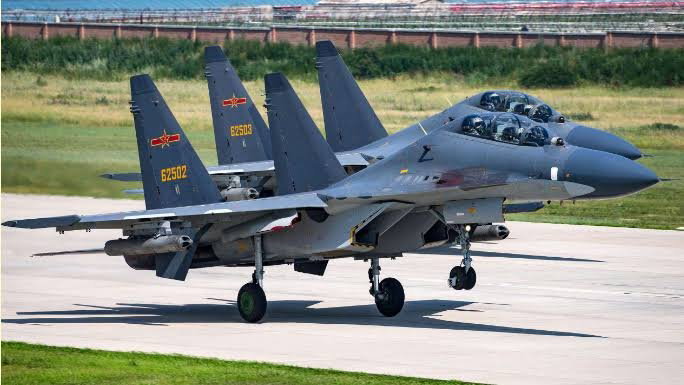
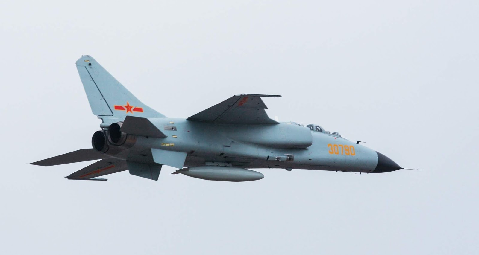
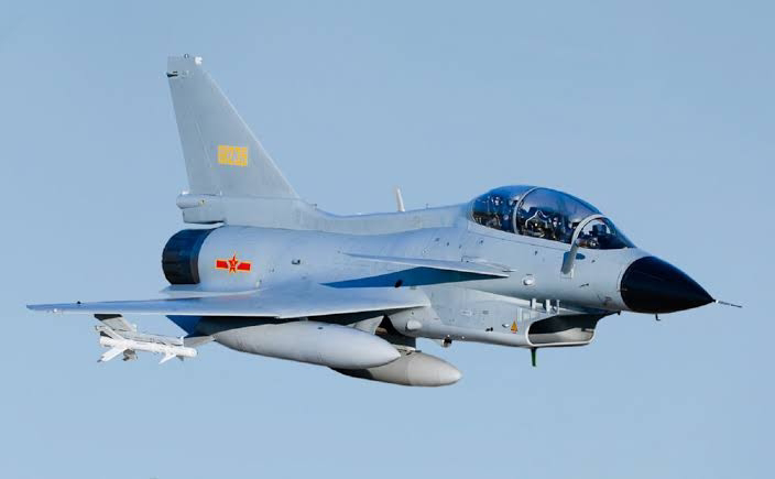
- China’s fighter planes are mostly the older 4G J-7s, which were derived from the Russian MIG-21 airframe. So, they probably show the same RCS of about 3m2 best case. Their J-10s have an RCS of 0.5 to 1.5m2. Their newer J-20 fighter has some flaws in its design, so it has an RCS about the same as older 4G fighters (about 1m2 to 3m2). We don’t have much data on their new J-31 (FC-31) fighters, but they did create some rippled exhaust nozzles on their engines that will reduce its rear-aspect reflections. If I had to guess, since the J-31 looks like the offspring of the F-35 and the PAK-FA (T-50), It might have an RCS in the range of 0.5 to 0.1m2, being generous. And, if China is doing so well with their stealth fighter designs, why did they just take delivery of four Russian SU-35s in December 2016? The frontal RCS of their new J-31 is certainly much better than the SU-35, if my guess is accurate, so they must want access to the Russian radar and on-board systems.
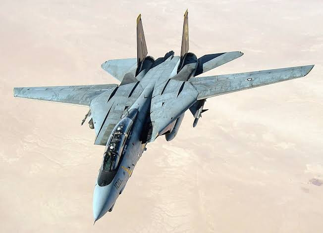
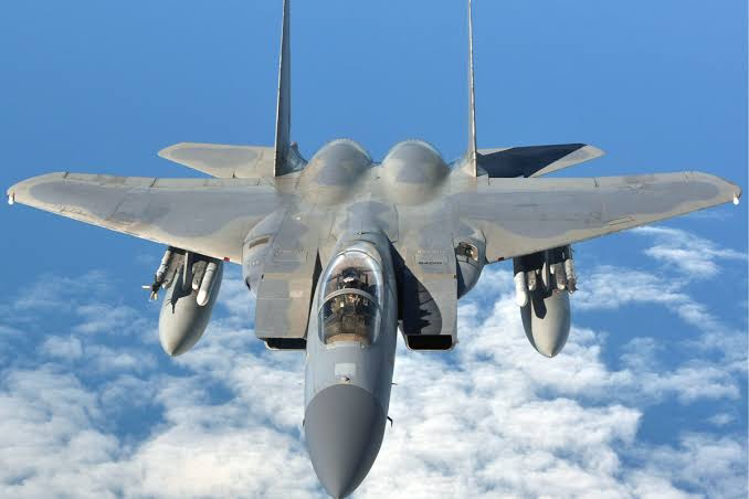
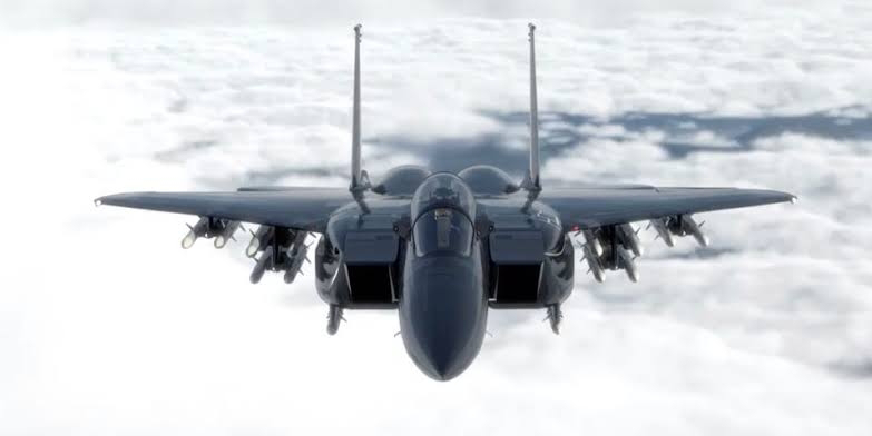
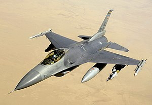
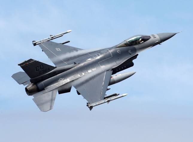
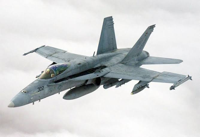
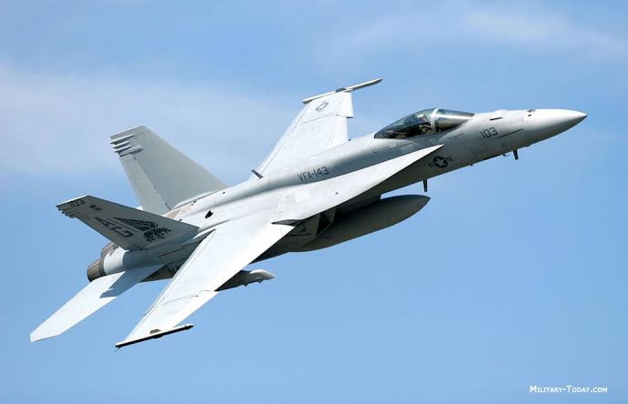
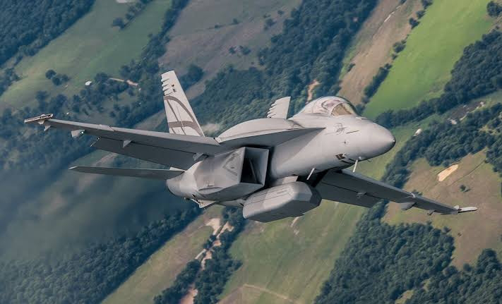
- Among the U.S. fighter planes, the 4G F-15 has an RCS of 25m2, not very impressive and bigger than the older Russian MIG fighters. The 4G F16 has an RCS of 5m2, better but still not great. The 4.5G F/A-18 Hornet Navy fighter jet has an RCS of 1m2, about the same as the Russian SU-34/35 and the Chinese J-20. The 5G F-35 has an RCS of 0.005m2, about the size of a golf ball. However, from the rear, it looks much bigger because of the exhaust nozzles, the same problem we saw with the 5G Russian PAK-FA (T-50). For comparison, the 5G F-22 has an RCS of 0.0001m2, about the size of a bumble bee. The U2 and SR-71 spy planes have an RCS of 0.01m2, about the size of a small bird. Our first stealth fighter/bomber was the F-117 Nighthawk from the 1980s. It has an RCS of 0.003m2, about the size of a hummingbird, and those F-117s hit more than 1,600 targets without being molested by Iraqi air defenses during the 1991 Gulf War.
We didn’t discuss long range bomber aircraft in the previous article, but it’s worth throwing those values in here for your reading enjoyment. The B-52 has an RCS of about 100m2. The B-1 bomber is 10m2. The B-2 bomber has an RCS of 0.0001m2, the same as the F-22, the size of a bumble bee. The new B-21 bomber, now being built by Northrop Grumman, is virtually invisible to UHF/VHF radar. It shows up about the size of a mosquito. I am forced to use one formula and do the calculations here, since the return signal is -70db for the B-21, and the RCS in square meters was not on the web anywhere: RCSsm=10db/10 = 10-70/10 = 10-7, or about 0.000001m2. If you ever wondered about it, that’s the size of a mosquito on radar.
Our major enemies fly terribly old and antiquated non-stealthy bomber aircraft. The Russians are still using propeller-driven aircraft like the TU-95 Bear. By comparison again, the RCS of a World War II B-25 prop-driven bomber is 3,100m2. The Russians also have their TU-160 jet-powered bombers in operation, and the Chinese have a similar elderly H-6 jet bomber. There are no good numbers for these antiquated airframes on the web, so I think they would have about the same RCS as a Hilton Hotel.
As you can tell from all these numbers, good stealth design requires that all weapons (missiles, bombs) be enclosed inside the airframe. Also, external auxiliary fuel tanks under the wings will make the aircraft light-up a radar screen since they increase RCS dramatically. And, you must pay attention to the exhaust nozzles of the engines if you want to remain unnoticed. Neither Russia nor China have been able to equal what the U.S. has done with stealth design and radar-absorbant coatings on fighter jets. And both are way behind our stealth bomber designs. Additionally, I must give my usual disclaimer here: there are multiple RCS numbers on the web. I chose the only ones available, the ones found the most in articles, or calculated them from the published db values.
Next time, we’ll take a look at aircraft carriers, and why we don't need them anymore. That should make the Navy nervous. And, sorry about the formulas and calculations. The readership numbers on this piece in the Mil-Embedded.com web stats will verify if the unwritten journalism laws are true.
 militaryembedded.com
One of the most simplified hopefully accurate information on STEALTH, regarding RCS comparisons.
Did you guys know even the ancient stealth airplane F-117 attacked 1600 targets inside HEAVILY AD armed Saddam's Iraq without ever being close to be in danger?
Will we be in any diffierent of a situation if finally impending war breaks out because of our countless potential conflict issues with Americans?
Radar cross section: The measure of stealth
BlogMarch 31, 2017
RAY ALDERMAN
VITA Standards Organization
WARFARE EVOLUTION BLOG: The primary measure of stealth, or low observability (LO), is the radar cross section (RCS) of the target, whether it?s aircraft, missiles, or ships. The radar pulse goes out from the transmitter, hits the target, and bounces back. The radar receiver measures the energy in the return signal in decibel (db) units, but that?s a hard way for normal people to visualize the size of a target. So, we must convert db to square meters (m2) to get the picture.
Here’s all the the conversion formulas you'll need if you enjoy lots of digits to the right of the decimal point. <http://www.alternatewars.com/BBOW/Radar/Decibels_Radars.htm>Instead of laboriously converting the db values for all the different fighter jets mentioned in my previous article, there's a nifty table with most of the conversions done for us. <http://www.globalsecurity.org/military/world/stealth-aircraft-rcs.htm> Using this table will also allow me to escape the clutches of the unwritten laws of journalism too. They state that readership will decline by 50 percent for every formula in an article, and by 75 percent if you show any calculations. Many good papers and articles exist on the web that expose the intricacies of RCS if you want to dig deeper into this topic. For this article, we’ll just use the m2 values from the table and skip the joys of the math.
To read more Warfare Evolution Blogs by Ray Alderman, click here.
Before we get into this, other complications need to be mentioned. The RCS of an aircraft depends on its aspect, the orientation of the target to the radar source. Any aircraft will have a smaller RCS from the front, and show-up bigger from the side or the rear. Looking at the table values, their numbers seem to be based on the frontal aspect, the lowest RCS of the aircraft. Also, some fighter jets have their largest RCS from the rear, due to the exhaust nozzles. And, RCS depends on the wavelength (frequency) of the radar signal and how far away the target is. But we’ll ignore these pesky details for now. Just consider the numbers we use here as the best RCS values for each aircraft. For comparison, an average man has an RCS of about 1m2.
- In my last blog, we talked about Russia’s older 4G MIG-XX, 4.5G SU-34/35, and 5G PAK-FA (T-50) fighter jets. The older 4G MIG platforms have an RCS of 15m2, down to 3m2 for the MIG-21. The SU-34s RCS is 1m2. SU-35s are 1m2 to 3m2, according to web sources. The PAK-FA (T-50) has an RCS of 0.5m2, about the same as a Tomahawk cruise missile. None of those planes are truly stealthy. Most of them are big fat targets to our advanced radars.
- China’s fighter planes are mostly the older 4G J-7s, which were derived from the Russian MIG-21 airframe. So, they probably show the same RCS of about 3m2 best case. Their J-10s have an RCS of 0.5 to 1.5m2. Their newer J-20 fighter has some flaws in its design, so it has an RCS about the same as older 4G fighters (about 1m2 to 3m2). We don’t have much data on their new J-31 (FC-31) fighters, but they did create some rippled exhaust nozzles on their engines that will reduce its rear-aspect reflections. If I had to guess, since the J-31 looks like the offspring of the F-35 and the PAK-FA (T-50), It might have an RCS in the range of 0.5 to 0.1m2, being generous. And, if China is doing so well with their stealth fighter designs, why did they just take delivery of four Russian SU-35s in December 2016? The frontal RCS of their new J-31 is certainly much better than the SU-35, if my guess is accurate, so they must want access to the Russian radar and on-board systems.
- Among the U.S. fighter planes, the 4G F-15 has an RCS of 25m2, not very impressive and bigger than the older Russian MIG fighters. The 4G F16 has an RCS of 5m2, better but still not great. The 4.5G F/A-18 Hornet Navy fighter jet has an RCS of 1m2, about the same as the Russian SU-34/35 and the Chinese J-20. The 5G F-35 has an RCS of 0.005m2, about the size of a golf ball. However, from the rear, it looks much bigger because of the exhaust nozzles, the same problem we saw with the 5G Russian PAK-FA (T-50). For comparison, the 5G F-22 has an RCS of 0.0001m2, about the size of a bumble bee. The U2 and SR-71 spy planes have an RCS of 0.01m2, about the size of a small bird. Our first stealth fighter/bomber was the F-117 Nighthawk from the 1980s. It has an RCS of 0.003m2, about the size of a hummingbird, and those F-117s hit more than 1,600 targets without being molested by Iraqi air defenses during the 1991 Gulf War.
We didn’t discuss long range bomber aircraft in the previous article, but it’s worth throwing those values in here for your reading enjoyment. The B-52 has an RCS of about 100m2. The B-1 bomber is 10m2. The B-2 bomber has an RCS of 0.0001m2, the same as the F-22, the size of a bumble bee. The new B-21 bomber, now being built by Northrop Grumman, is virtually invisible to UHF/VHF radar. It shows up about the size of a mosquito. I am forced to use one formula and do the calculations here, since the return signal is -70db for the B-21, and the RCS in square meters was not on the web anywhere: RCSsm=10db/10 = 10-70/10 = 10-7, or about 0.000001m2. If you ever wondered about it, that’s the size of a mosquito on radar.
Our major enemies fly terribly old and antiquated non-stealthy bomber aircraft. The Russians are still using propeller-driven aircraft like the TU-95 Bear. By comparison again, the RCS of a World War II B-25 prop-driven bomber is 3,100m2. The Russians also have their TU-160 jet-powered bombers in operation, and the Chinese have a similar elderly H-6 jet bomber. There are no good numbers for these antiquated airframes on the web, so I think they would have about the same RCS as a Hilton Hotel.
As you can tell from all these numbers, good stealth design requires that all weapons (missiles, bombs) be enclosed inside the airframe. Also, external auxiliary fuel tanks under the wings will make the aircraft light-up a radar screen since they increase RCS dramatically. And, you must pay attention to the exhaust nozzles of the engines if you want to remain unnoticed. Neither Russia nor China have been able to equal what the U.S. has done with stealth design and radar-absorbant coatings on fighter jets. And both are way behind our stealth bomber designs. Additionally, I must give my usual disclaimer here: there are multiple RCS numbers on the web. I chose the only ones available, the ones found the most in articles, or calculated them from the published db values.
Next time, we’ll take a look at aircraft carriers, and why we don't need them anymore. That should make the Navy nervous. And, sorry about the formulas and calculations. The readership numbers on this piece in the Mil-Embedded.com web stats will verify if the unwritten journalism laws are true.
Radar cross section: The measure of stealth - Military Embedded Systems
WARFARE EVOLUTION BLOG: The primary measure of stealth, or low observability (LO), is the radar cross section (RCS) of the target, whether it?s aircraft, missiles, or ships. The radar pulse goes out from the transmitter, hits the target, and bounces back. The radar receiver measures the energy...
militaryembedded.com
Last edited:


![F-16CM - Have Glass V [USAF/Staff Sgt Trevor T McBride]](/proxy.php?image=https%3A%2F%2Ffullfatthings-keyaero.b-cdn.net%2Fsites%2Fkeyaero%2Ffiles%2Finline-images%2F1%2529%2520201222-F-ER377-0880.jpg&hash=3c3c635389c5a241e770dc2246a2e4be "F-16CM - Have Glass V [USAF/Staff Sgt Trevor T McBride]")
![F-16C Have Glass [US ANG/Senior Airman Christi A Richter]](/proxy.php?image=https%3A%2F%2Ffullfatthings-keyaero.b-cdn.net%2Fsites%2Fkeyaero%2Ffiles%2Finline-images%2F13%2529%2520LM%2520F-16CM%2520OH%25205827493.jpg&hash=f09236532cca1a76ec0c9e0e128fddad "F-16C Have Glass [US ANG/Senior Airman Christi A Richter]")
![F-16C Have Glass [US ANG/Tech Sgt Luke Olsen]](/proxy.php?image=https%3A%2F%2Ffullfatthings-keyaero.b-cdn.net%2Fsites%2Fkeyaero%2Ffiles%2Finline-images%2F14%2529%2520LM%2520F-16C%2520SD%25203729248.jpg&hash=14162172fa737ee23ffc0b0c90cf98d4 "F-16C Have Glass [US ANG/Tech Sgt Luke Olsen]")
![F-16s Have Glass [USAF]](/proxy.php?image=https%3A%2F%2Ffullfatthings-keyaero.b-cdn.net%2Fsites%2Fkeyaero%2Ffiles%2Finline-images%2F10%2529%2520LM%2520F-16C%2520MN%25205942954.jpg&hash=5adfbfd2abe51782ec447840fcfec215 "F-16s Have Glass [USAF]")
![F-16C Have Glass [US ANG/Senior Master Sgt Beth Holliker]](/proxy.php?image=https%3A%2F%2Ffullfatthings-keyaero.b-cdn.net%2Fsites%2Fkeyaero%2Ffiles%2Finline-images%2F11%2529%2520LM%2520F-16CM%2520OH%25206209167.jpg&hash=4b5ae389f4bb667300f3b80b6bf2a19d "F-16C Have Glass [US ANG/Senior Master Sgt Beth Holliker]")
![F-35B [MoD Crown Copyright]](/proxy.php?image=https%3A%2F%2Ffullfatthings-keyaero.b-cdn.net%2Fsites%2Fkeyaero%2Ffiles%2Finline-images%2F3%2529%2520MRM-OFFICIAL-20200903-0416-0397%2520%25283%2529.jpg&hash=3c74533fdc14656e0c38e6d729760ffd "F-35B [MoD Crown Copyright]")
![F-16 Have Glass [USAF/Senior Airman Michael Cowley]](/proxy.php?image=https%3A%2F%2Ffullfatthings-keyaero.b-cdn.net%2Fsites%2Fkeyaero%2Ffiles%2Finline-images%2F6%2529%2520LM%2520F-16CM%2520SW%2520worn_Falcon_Fighting_-_091119-F-7323C-292.jpg&hash=575939eb645fae3c66e3775aeb37d804 "F-16 Have Glass [USAF/Senior Airman Michael Cowley]")
![F-16 Have Glass [US ANG/Senior Master Sgt Vincent De Groot]](/proxy.php?image=https%3A%2F%2Ffullfatthings-keyaero.b-cdn.net%2Fsites%2Fkeyaero%2Ffiles%2Finline-images%2F15%2529%2520191217-Z-KZ880-047.jpg&hash=900e5d611b2409703f547c9e663fd867 "F-16 Have Glass [US ANG/Senior Master Sgt Vincent De Groot]")
![F-16CMs Have Glass [USAF/Tech Sgt Gregory Brook]](/proxy.php?image=https%3A%2F%2Ffullfatthings-keyaero.b-cdn.net%2Fsites%2Fkeyaero%2Ffiles%2Finline-images%2F4%2529%2520170721-F-OH871-0390.jpg&hash=8010d285c46b32c835dd5bcec2714cd5 "F-16CMs Have Glass [USAF/Tech Sgt Gregory Brook]")
![F-16 stealth testbed [Lockheed]](/proxy.php?image=https%3A%2F%2Ffullfatthings-keyaero.b-cdn.net%2Fsites%2Fkeyaero%2Ffiles%2Finline-images%2F2%2529%25202010_f16_dsi_02_1267828237_7281%2520%25283%2529.jpg&hash=390e3f5a109428220465331fa438aa20 "F-16 stealth testbed [Lockheed]")
![F-22A Raptor [USAF/Staff Sgt Vernon Young Jr]](/proxy.php?image=https%3A%2F%2Ffullfatthings-keyaero.b-cdn.net%2Fsites%2Fkeyaero%2Ffiles%2Finline-images%2F8%2529%2520F-22%25201317495.jpg&hash=634163c6be6155c4ab0902fdbbe9378e "F-22A Raptor [USAF/Staff Sgt Vernon Young Jr]")
![F-22A Raptor [USAF/Staff Sgt Vernon Young Jr]](/proxy.php?image=https%3A%2F%2Ffullfatthings-keyaero.b-cdn.net%2Fsites%2Fkeyaero%2Ffiles%2Finline-images%2F8a%2529%2520F-22%25201317491.jpg&hash=3153ee2f133385445f2db36ab6a7bce2 "F-22A Raptor [USAF/Staff Sgt Vernon Young Jr]")
![F-16CMs - Have Glass II [USAF/Airman 1st Class Dillon Davis]](/proxy.php?image=https%3A%2F%2Ffullfatthings-keyaero.b-cdn.net%2Fsites%2Fkeyaero%2Ffiles%2Finline-images%2F5%2529%2520LM%2520F-16CM%2520SP%2520have%2520glass%2520II%2520663164.jpg&hash=ce5931e7c8f3d58e1a5abef58429057f "F-16CMs - Have Glass II [USAF/Airman 1st Class Dillon Davis]")