T

Latest Thread
You are using an out of date browser. It may not display this or other websites correctly.
You should upgrade or use an alternative browser.
You should upgrade or use an alternative browser.
USA United States Air Force
Low IQ Techie
Active member

It is personal view of the artist, otherwise the rear half design can be anything.Looks kinda odd for a 6th gen.
Let's see for how many weeks or months USA will hide its jet.


Low IQ Techie
Active member
I think they'll make 2 jets - 1 engine exportable future of JSF & 2 engine domestic future of ATF. Time will tell soon.
Low IQ Techie
Active member
Another artist's good imagination:
> This is tandem tri-plane, but putting canard just in front of intake could obstruct airflow, unless onlyouter 2/3rd or half of canard moves.
> Bcoz of darkened flag in poster, some people are still speculating small all-moving rudders.
> Like Bird-of-Prey the wing can still be slightly tilted up with with drooped winglet, but He forgot to allign the bend-axis longitudinally parallel to length. Such wing adds to stability while a fighter needs to be unstable for agility.
> Such platipus like flatter nose could mean lesser pitch agility & little more RCS return by nose.
> Overall this looks like 1 engine exportable jet. I wonder how in Trump's words "nothing even comes close from speed to maneuverability to payload" & this is "most advanced, capable, lethal".
Low IQ Techie
Active member
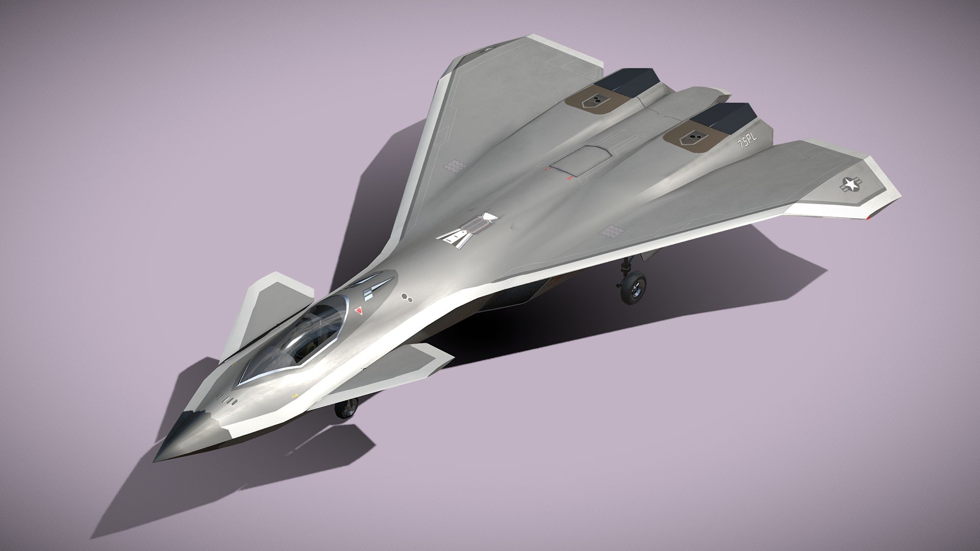
Another artist imagines F-47 little longer, dihedral wing with anhedral winglet.
The wing root is shifted back & intakes are also much behind, not enough space for serpentine duct, so engine would be visible.
Engine bays are apart & middle space filled like in Su-57, so might have tandem IWBs.
Perfect side, front, bottom images not available.


 sketchfab.com

The wing root is shifted back & intakes are also much behind, not enough space for serpentine duct, so engine would be visible.
Engine bays are apart & middle space filled like in Su-57, so might have tandem IWBs.
Perfect side, front, bottom images not available.
Boeing F-47 Thunderstorm NGAD | 3D model
Model available for download in Autodesk FBX format. Visit CGTrader and browse more than 1 million 3D models, including 3D print and real-time assets
www.cgtrader.com
Boeing F-47 Thunderstorm NGAD - 3D model by NETRUNNER_pl
Boeing F-47 Thunderstorm NGAD Lowpoly model of new concept american stealth fighter The Boeing F-47 is a 6-generation fighter aircraft developed for the U.S. Air Force under the Next Generation Air Dominance (NGAD) program. It’s designed to succeed the F-22 Raptor, with enhanced stealth...
sketchfab.com
Low IQ Techie
Active member
Some 3D artist imagined & made 3D model & animation of F-47, whose fuselage looks like F/A-XX concept, upward tilted wings remind of Bird-of-Prey, engine bay hump reminds of YF-23.
So F-47 NGAD = F/A-XX + BoP + YF-23.
I'm putting a smaller collage as the images are huge, bigger than the collage.
View attachment 74224
Some selected screenshots from animation showing specific angles to show airframe shape, parts:
View attachment 74225
The artist has updated a modified version w/o canard stating that USN doesn't wan't canards.
Well, this is opposite expectation if USAF wants canards but not USN bcoz the wing leading edge has high sweep angle means higher landing speed w/o canard.
I'm posting a collage again as the images are huge.
> Perhaps the nose & chine need more blending like in Rodrigo Avellas F/A-X concept for bigger & wider coverage radar.
> Wings have been made little Lambda style than Delta earlier.
> There doesn't seem to be any winglet.
> Intakes have DSI. The intake lower edge is ahead of upper edge (blended with wing root). This can be a problem if high AoA & tight turn is desired as some air can slip out over wing causing insufficient air flow & compressor stall. Giving aux-intakes below or moving lip like in EF-2000 would increase complexity & RCS.
> Parallel IWB not tandem & SWB have been marked.
> Engine bays quite far separated, the duct may not be serpentine enough, engine would be visible.
> Exhaust look like that of YF-23 w/o TVC.
It seems that this is going to become a standard look of all 6gen jets.

Blame game already started on who's copying whom.
 It is bcoz of planform shaping fundamental started since 5gen.

Low IQ Techie
Active member
The model in the CGI:
Low IQ Techie
Active member
For common people like us it can actually be a big headache
 to imagine & estimate a new jet in 2D, unless we know how to use 3D CAD S/w.
Most 3D artists also make models w/o thinking too much themselves.
Let's take F-22 as foundation reference.
If we wan't a better TE jet as per 6gen features of more capacity of weapons, fuel, new components, then it'll be bigger. So if the size/volume/weight is more & if same or more dry/wet ATWR (Airframe Thrust to Weight Ratio) needs to be maintained, then more airframe weight -> more thrust -> more air -> more area of intake, duct & inlet.
For idea, F-22's F119 Vs F-35's F-135 engines: 100cm Vs 109cm inlet dia., 116/128 KN Vs 156/191 KN dry/wet thrust. 9% more inlet dia., almost 19% more area, 10.3% more dry thrust, 22.4% more wet thrust.
There is no fixed formula b/w area of intake/duct/inlet & thrust, let's assume 1:1 ratio in increase for easy understanding. So if we fit F-22 with a bigger & 33% better engine of 156*1.33= 207.5 KN, the challenges are -
- increase air flow by 33%, means increase area of intake, duct & inlet by 33%. Inlet diameter increases by square-root(1.33) times or 15.32%.
- increase payload & range, means lengthen the jet.
- restrict airframe volume to 133%.
- restrict airframe height to that of F-22 if possible.
If the airframe expands only in width & height then it is easy to estimate.
If the airframe expands in all 3 XYZ axis in same ratio then also it is easy to estimate.
But if all 3 axis have different ratios then we have to be careful not to eceed new volume/weight.
Option 1 - stretch the airframe length only by 33%, which will need tandem IWB for extra AAMs.
Option 2 - stretch the airframe width only by 33%, which can adjust 4 more AAMs easily.
Option 3 - stretch both airframe width & length by ratio such that X*Y=1.33, like 1.1*1.2 or 10% X 20%.
Exploring option-1 1st, the fuselage width remains same, area of intake, duct & engine increased, again there are 3 sub-options:
1A - expand area in width & height by 15.32%, engine can be pushed down, but intake slightly portrudes down & out, duct above IWB is manageable.
1B - expand area in height only by 33%, engine can be pushed down, but intake portrudes down more & duct above IWB produces bump.
1C - expand area in width only by 33%, engine is pushed down, intake portrudes out sideways but manageable, duct above IWB is manageable.
I don't have 3D CAD S/w, so I put the above options 3 sub-options in approximate cross section diagrams of F-22:

So we see that increased size/volume of 1 or some components or system affects other parts & entire airframe.
The engine power, size, weight is dictating design of stealth jet if same ATWR has to be maintained.
to imagine & estimate a new jet in 2D, unless we know how to use 3D CAD S/w.Most 3D artists also make models w/o thinking too much themselves.
Let's take F-22 as foundation reference.
If we wan't a better TE jet as per 6gen features of more capacity of weapons, fuel, new components, then it'll be bigger. So if the size/volume/weight is more & if same or more dry/wet ATWR (Airframe Thrust to Weight Ratio) needs to be maintained, then more airframe weight -> more thrust -> more air -> more area of intake, duct & inlet.
For idea, F-22's F119 Vs F-35's F-135 engines: 100cm Vs 109cm inlet dia., 116/128 KN Vs 156/191 KN dry/wet thrust. 9% more inlet dia., almost 19% more area, 10.3% more dry thrust, 22.4% more wet thrust.
There is no fixed formula b/w area of intake/duct/inlet & thrust, let's assume 1:1 ratio in increase for easy understanding. So if we fit F-22 with a bigger & 33% better engine of 156*1.33= 207.5 KN, the challenges are -
- increase air flow by 33%, means increase area of intake, duct & inlet by 33%. Inlet diameter increases by square-root(1.33) times or 15.32%.
- increase payload & range, means lengthen the jet.
- restrict airframe volume to 133%.
- restrict airframe height to that of F-22 if possible.
If the airframe expands only in width & height then it is easy to estimate.
If the airframe expands in all 3 XYZ axis in same ratio then also it is easy to estimate.
But if all 3 axis have different ratios then we have to be careful not to eceed new volume/weight.
Option 1 - stretch the airframe length only by 33%, which will need tandem IWB for extra AAMs.
Option 2 - stretch the airframe width only by 33%, which can adjust 4 more AAMs easily.
Option 3 - stretch both airframe width & length by ratio such that X*Y=1.33, like 1.1*1.2 or 10% X 20%.
Exploring option-1 1st, the fuselage width remains same, area of intake, duct & engine increased, again there are 3 sub-options:
1A - expand area in width & height by 15.32%, engine can be pushed down, but intake slightly portrudes down & out, duct above IWB is manageable.
1B - expand area in height only by 33%, engine can be pushed down, but intake portrudes down more & duct above IWB produces bump.
1C - expand area in width only by 33%, engine is pushed down, intake portrudes out sideways but manageable, duct above IWB is manageable.
I don't have 3D CAD S/w, so I put the above options 3 sub-options in approximate cross section diagrams of F-22:
So we see that increased size/volume of 1 or some components or system affects other parts & entire airframe.
The engine power, size, weight is dictating design of stealth jet if same ATWR has to be maintained.

For common people like us it can actually be a big headache
Most 3D artists also make models w/o thinking too much themselves.
Let's take F-22 as foundation reference.
If we wan't a better TE jet as per 6gen features of more capacity of weapons, fuel, new components, then it'll be bigger. So if the size/volume/weight is more & if same or more dry/wet ATWR (Airframe Thrust to Weight Ratio) needs to be maintained, then more airframe weight -> more thrust -> more air -> more area of intake, duct & inlet.
For idea, F-22's F119 Vs F-35's F-135 engines: 100cm Vs 109cm inlet dia., 116/128 KN Vs 156/191 KN dry/wet thrust. 9% more inlet dia., almost 19% more area, 10.3% more dry thrust, 22.4% more wet thrust.
There is no fixed formula b/w area of intake/duct/inlet & thrust, let's assume 1:1 ratio in increase for easy understanding. So if we fit F-22 with a bigger & 33% better engine of 156*1.33= 207.5 KN, the challenges are -
- increase air flow by 33%, means increase area of intake, duct & inlet by 33%. Inlet diameter increases by square-root(1.33) times or 15.32%.
- increase payload & range, means lengthen the jet.
- restrict airframe volume to 133%.
- restrict airframe height to that of F-22 if possible.
If the airframe expands only in width & height then it is easy to estimate.
If the airframe expands in all 3 XYZ axis in same ratio then also it is easy to estimate.
But if all 3 axis have different ratios then we have to be careful not to eceed new volume/weight.
Option 1 - stretch the airframe length only by 33%, which will need tandem IWB for extra AAMs.
Option 2 - stretch the airframe width only by 33%, which can adjust 4 more AAMs easily.
Option 3 - stretch both airframe width & length by ratio such that X*Y=1.33, like 1.1*1.2 or 10% X 20%.
Exploring option-1 1st, the fuselage width remains same, area of intake, duct & engine increased, again there are 3 sub-options:
1A - expand area in width & height by 15.32%, engine can be pushed down, but intake slightly portrudes down & out, duct above IWB is manageable.
1B - expand area in height only by 33%, engine can be pushed down, but intake portrudes down more & duct above IWB produces bump.
1C - expand area in width only by 33%, engine is pushed down, intake portrudes out sideways but manageable, duct above IWB is manageable.
I don't have 3D CAD S/w, so I put the above options 3 sub-options in approximate cross section diagrams of F-22:
View attachment 74373
So we see that increased size/volume of 1 or some components or system affects other parts & entire airframe.
The engine power, size, weight is dictating design of stealth jet if same ATWR has to be maintained.
There are also things that cascade to aircraft stability and control when you fudge around dimensionally.
You create more of a lifting surface with say wideness relative to the C of G that needs to be taken into account in stabilizer sizing and placement and so on.
If the C of G itself is moved, then the whole moment diagram is changed and this causes drastic size changes for same reason.
Low IQ Techie
Active member
Perhaps the easiest full-scale F-47 look-alike TD/prototype modified from existing jet F-22.
The wing & tail-stab positions are interchanged & rudders removed.
Making its front, side, bottom views w/o 3D S/w by just imagining is very tedious at this time, what i used to do on graph sheets in school-days in 1990s watching F-117, B-2, deveoping F-22 on Discovery channel. The good old days


Anyways, i wonder if LM built such a jet for competition or research.


The wing & tail-stab positions are interchanged & rudders removed.
Making its front, side, bottom views w/o 3D S/w by just imagining is very tedious at this time, what i used to do on graph sheets in school-days in 1990s watching F-117, B-2, deveoping F-22 on Discovery channel.
The good old days Anyways, i wonder if LM built such a jet for competition or research.
Low IQ Techie
Active member
Here is the V2 with wing lengthened, leading edge angle increased.
The canard had to be shortened, maintaining planform design. With TVC nozzles, big canards may not be required.
I made the nose narrower, triangular to lessen drag & RCS.
Comparison with V1 is also shown.
The day i'll get a light weight, old, stable version of some 3D CAD S/w for my old laptop, i'll start translating these into 3D.
Feedbacks are welcome, i'm making a V3 also.
Low IQ Techie
Active member
YF-23's designer's conceptual view of F-47 NGAD:
 aviationweek.com

F-22 is 62 ft. long & the drawing is quoted at 61 ft. which i don't is possible for a 6gen specs with bigger better engine, more fuel, weapons, equipment.
NGAD should be expected to be bigger than F-22. So, following is comparison with F-22 after comparing cockpit.


YF-23 Designer Offers His Take On Boeing’s F-47 NGAD Configuration | Aviation Week
Renowned aircraft designer Darold Cummings explores questions raised by Boeing’s F-47 NGAD design.
aviationweek.com
F-22 is 62 ft. long & the drawing is quoted at 61 ft. which i don't is possible for a 6gen specs with bigger better engine, more fuel, weapons, equipment.
NGAD should be expected to be bigger than F-22. So, following is comparison with F-22 after comparing cockpit.
Low IQ Techie
Active member
Artist Rodrigo Avella & some others made a CAD earlier speculated to be tail-less F/A-XX with canards.

Almost same model w/o canards have been depicted as NGAD, sometimes with rudders.

Comparing it with F-22, equalized at cockpit, looks like following:


Almost same model w/o canards have been depicted as NGAD, sometimes with rudders.
Comparing it with F-22, equalized at cockpit, looks like following:

upgraded new f35 coming.
plus
twin engined F35 = F55
a new upgraded f22 to come as well
all from the mouth of Mr Trump
plus
twin engined F35 = F55
a new upgraded f22 to come as well
all from the mouth of Mr Trump
Low IQ Techie
Active member
Here is the V2 with wing lengthened, leading edge angle increased.
The canard had to be shortened, maintaining planform design. With TVC nozzles, big canards may not be required.
I made the nose narrower, triangular to lessen drag & RCS.
Comparison with V1 is also shown.
The day i'll get a light weight, old, stable version of some 3D CAD S/w for my old laptop, i'll start translating these into 3D.
Feedbacks are welcome, i'm making a V3 also.
View attachment 74516
Version 3a & 3b with Lambda wing getting popular & nose triangular & double delta.
Low IQ Techie
Active member
I should have posted this before F-47 announcement when advertisements about the preliminary NGAD design speculations of delta, cropped diamond wings were floating. So Versions 4, 5 related to that.
And then V6c like SR-72, Darkstar.


And then V6c like SR-72, Darkstar.

Low IQ Techie
Active member
Recently RTX (Raytheon) put a small video on their website which showcases a CGI of F-47 NGAD prototype perhaps.
(https://www.rtx.com/news/2026/02/18/fast-tracking-the-fighter-jet-engine-of-the-future)
Need to scroll down to middle of webpage
Screenshots from video-


It is difficult to imagine 2D from 3D.
Observations -
- superimposed XA engine doesn't match the CG jet aiframe
- YF-23 like diamond wing
- humped engine bays
- ventral tail strakes
- pitot's tube
- blade antenna behind cockpit
- anhedral wing
- horizontal or slightly dihedral canard
- 4x bigger heat exchanger exhaust dorsal grill b/w engines
- Animation mistake - for rolling right, the left flaperon, aeleron should move down, the right ones should move up.
So these features indicate a X-jet as it is said to be flying secretly since 5 years.
These days original photos & videos can be edited at will.
So either it could be an initial X-jet, a modified F-22 to keep it economical, or it is just CG by a quick edit of F-22.
Translating its view from roughly 45 degrees in azimuth b/w side & rear to 2D, a very quick edit in MS Paint might look like this -

(https://www.rtx.com/news/2026/02/18/fast-tracking-the-fighter-jet-engine-of-the-future)
Need to scroll down to middle of webpage
Screenshots from video-
It is difficult to imagine 2D from 3D.
Observations -
- superimposed XA engine doesn't match the CG jet aiframe
- YF-23 like diamond wing
- humped engine bays
- ventral tail strakes
- pitot's tube
- blade antenna behind cockpit
- anhedral wing
- horizontal or slightly dihedral canard
- 4x bigger heat exchanger exhaust dorsal grill b/w engines
- Animation mistake - for rolling right, the left flaperon, aeleron should move down, the right ones should move up.
So these features indicate a X-jet as it is said to be flying secretly since 5 years.
These days original photos & videos can be edited at will.
So either it could be an initial X-jet, a modified F-22 to keep it economical, or it is just CG by a quick edit of F-22.
Translating its view from roughly 45 degrees in azimuth b/w side & rear to 2D, a very quick edit in MS Paint might look like this -